SMT Production Line Purchasing Strategy for Portable Power Bank Factories: A Complete Guide

Your power bank orders are piling up, but your current production line can’t keep pace. Component placement errors are eating into your margins. Battery safety compliance feels like a moving target. And every time you switch between 10,000mAh and 20,000mAh models, your line sits idle for hours. These aren’t just operational headaches—they’re profit killers in a market where margins are already razor-thin.
We’ve seen this story play out across dozens of power bank factories. The good news? Most of these problems trace back to one root cause: an SMT line that wasn’t designed for the unique demands of portable power manufacturing. The better news? Getting it right doesn’t require a million-dollar gamble. Whether you’re building a compact electronics production line from scratch or retrofitting existing capacity, the right equipment configuration can cut your defect rates by 40%, reduce changeover time from 90 minutes to 15, and put you back in control of your production schedule. This guide walks through exactly what that looks like—based on real implementations, not marketing brochures.
Table of Contents
1. Understanding Power Bank PCB Assembly Requirements
Power bank PCBs differ significantly from standard consumer electronics boards. In our experience working with compact electronics manufacturers, these devices typically feature 4-6 layer PCBs with component densities reaching 40-60 components per square inch. The main board integrates battery management systems (BMS), USB-C/PD controllers, wireless charging modules, and protection circuits—all within a footprint often smaller than a credit card.
The assembly complexity stems from several factors. First, the BMS chipset requires precise placement accuracy within ±25 microns, as these components handle critical battery protection functions. Second, power banks incorporate both large passive components (inductors, capacitors for power regulation) and tiny 0201/01005 passives for control circuits. This mix demands placement equipment capable of handling component sizes ranging from 0.4mm×0.2mm to 12mm×12mm on the same board.

Thermal management presents another challenge. Power banks generate significant heat during fast charging (18W-100W+), requiring careful consideration of component placement and solder joint reliability. The proximity of heat-sensitive battery protection ICs to power inductors demands precise process control during reflow. In actual production environments, we’ve observed that profiling the reflow oven for mixed component thermal masses can reduce defect rates by 30-40% compared to standard profiles.
Production volume considerations also drive equipment selection. A mid-sized power bank factory typically produces 5,000-20,000 units daily, requiring SMT lines capable of sustaining 40,000-80,000 CPH (components per hour) across multiple product variants. This volume range sits in a sweet spot where semi-automatic changeover capabilities provide significant ROI without requiring fully automated solutions that might be overkill for typical product lifecycles of 12-18 months.
2. Key Equipment Selection for Power Bank SMT Lines
Selecting the right equipment mix requires balancing throughput, flexibility, and capital investment. Based on our experience with similar compact electronics manufacturing setups, here’s a practical configuration framework:
Stencil Printer: For power bank production, a high-precision stencil printer with automatic solder paste inspection (SPI) integration is essential. Look for machines offering ±12.5 micron alignment accuracy and automatic under-stencil cleaning cycles every 3-5 prints. The fine-pitch QFN packages common in BMS chips demand consistent paste volume control—typically 60-80% of aperture area depending on component pitch. In practice, printers with closed-loop pressure control and 2D/3D SPI feedback can reduce solder defects by 45-60% compared to basic pneumatic systems.
Pick and Place Machine: The placement equipment forms the heart of your investment. For power bank lines, we recommend configurations supporting minimum 0201 (imperial) components with placement accuracy of ±35 microns at 3 sigma. A dual-gantry machine with 80+ feeder slots provides adequate flexibility for typical power bank BOMs (80-120 unique components) while maintaining 25,000-35,000 CPH per machine. Consider machines with quick-change feeder carts—this feature alone can reduce changeover time from 90 minutes to 15-20 minutes when switching between different capacity models (10,000mAh vs 20,000mAh variants).

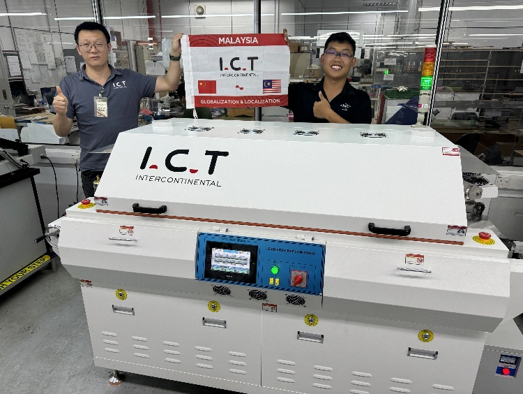
Reflow Oven: Given the thermal sensitivity of battery protection circuits combined with large thermal mass components, a 10-zone reflow oven with nitrogen capability offers the best process window. Nitrogen atmosphere reduces oxidation on fine-pitch QFN pads—a common issue with BMS chips that can lead to latent field failures. Profile flexibility matters too; you’ll need to accommodate both lead-free standard profiles and modified profiles for boards with polymer-filled vias or heavy copper layers common in high-current power bank designs.
AOI and Testing: Automated optical inspection should cover 100% of placements before reflow (pre-reflow AOI) and after reflow (post-reflow AOI). For power banks, pay special attention to polarity checking—reversed diodes or capacitors in charging circuits can create safety hazards. In-line testing should include ICT (In-Circuit Test) capabilities for BMS firmware verification and basic functional testing before battery connection.
3. Space Optimization: Compact Factory Layout Strategies
Power bank factories often operate in regions where floor space commands premium pricing. A typical compact SMT line layout for power bank production can fit within 150-200 square meters while maintaining efficient material flow.
The linear layout remains most common: Stencil Printer → SPI → Pick & Place → Pre-reflow AOI → Reflow Oven → Post-reflow AOI → Unloader. However, U-shaped or L-shaped configurations can reduce floor space by 20-30% when ceiling height permits overhead return conveyors. In one recent implementation for a 10,000-unit/day facility, we arranged equipment in an L-configuration that reduced the production area from 220m² to 165m² while actually improving operator access for maintenance.

Material logistics deserve careful planning. Power bank PCBs typically arrive in panelized form (2-4 boards per panel), requiring depaneling after SMT. Positioning the depaneling station immediately after the SMT line, rather than in a separate area, can reduce WIP (work-in-progress) inventory by 40-50%. Similarly, component kitting areas should be within 10 meters of the line to minimize feeder replenishment time—a critical factor when producing multiple variants with different battery capacities and port configurations.
Environmental control matters more than many realize. Power bank assembly requires maintaining 45-65% relative humidity to prevent ESD damage and solder paste drying. In compact facilities, dedicating 15-20% of floor space to climate control infrastructure (air handling, humidity systems) is a worthwhile investment that typically pays for itself within 12-18 months through reduced defect rates and rework.
Need Help Optimizing Your Factory Layout?
Every facility has unique constraints—column spacing, ceiling height, existing workflow patterns. I.C.T provides free layout design consultations based on your actual floor plans and production targets. Our engineers have optimized SMT layouts for over 200 compact electronics factories worldwide.
4. Balancing Flexibility and Cost: A Strategic Approach
The power bank market evolves rapidly—capacity demands increase, charging protocols change (QC3.0 to PD3.0 to PPS), and form factors shift. Your SMT line investment strategy must accommodate this volatility without requiring complete retooling every 18 months.
Modular equipment selection provides the answer. Rather than purchasing a monolithic high-speed line optimized for a single product, consider a modular approach: one high-flexibility line capable of handling prototypes and small batches (1,000-5,000 units), plus one high-throughput line for stable, high-volume products. This configuration typically adds 15-20% to initial capital investment but reduces changeover costs by 60-70% and extends equipment useful life by 3-5 years.

ROI calculations for power bank SMT lines should consider several variables beyond simple throughput. Labor costs in your region, electricity rates, and defect rate targets all significantly impact payback periods. In our experience, a well-configured mid-range line (approximately $800K-$1.2M investment) serving a 15,000-unit/day factory typically achieves ROI within 18-24 months when replacing manual assembly or outsourced SMT. However, if you work with I.C.T to provide your production line, the cost can be reduced to $150K-$600K while maintaining the same performance and quality standards.
Consider also the hidden costs of insufficient flexibility. A line optimized solely for today’s 10,000mAh standard may require $50K-$100K in feeder and program changes when 20,000mAh models with additional protection circuits become the market norm. Equipment with broader component range capabilities and software-based changeover procedures provides insurance against these transition costs.
5. Quality Control and Safety Compliance
Power banks fall under strict safety regulations—UN38.3 for transportation, IEC 62133 for battery safety, and various regional certifications (UL, CE, PSE). Your SMT process directly impacts compliance through solder joint reliability, component placement accuracy, and traceability.
Process control starts with solder paste management. Power bank PCBs often use 0.3-0.5mm pitch QFN packages for BMS controllers, requiring Type 4 or Type 5 solder paste with tight particle size distribution. Implementing automatic paste height monitoring and viscosity checking prevents defects that could lead to field failures. In production environments, we’ve seen paste management systems reduce voiding in QFN ground pads from 15-20% to under 5%—a critical improvement for thermal performance in high-current charging circuits.

Traceability requirements are increasing across the industry. Full component-level traceability (knowing which reel fed which component on which board) is becoming standard for insurance and liability reasons. Modern SMT assembly solutions should include MES (Manufacturing Execution System) integration capable of recording feeder positions, component lot numbers, and placement data for every board. This level of traceability adds 5-8% to equipment costs but can reduce liability exposure and simplify recall procedures if quality issues emerge.
Finally, consider the downstream impact of SMT quality. A defect escaping the SMT line and reaching final assembly with battery installation becomes exponentially more expensive to address. The cost ratio is roughly 1:10:100—fixing a defect at SMT costs $1, at final assembly costs $10, and in the field costs $100+ including warranty and reputation damage. This math justifies investment in comprehensive AOI and testing even when it extends cycle time by 10-15%.
Frequently Asked Questions
Q1: What is the typical investment range for a power bank SMT production line?
A complete SMT line for power bank manufacturing typically ranges from $500K to $1.5M depending on automation level and throughput requirements. Entry-level configurations handling 5,000-8,000 units daily start around $500K-$700K, while high-volume lines producing 20,000+ units daily with full automation may reach $1.2M-$1.5M. This includes stencil printer, pick-and-place machines, reflow oven, AOI systems, and conveyors. Contact I.C.T engineers for a detailed quote based on your specific production targets.
Q2: How long does it take to change over between different power bank models?
With modern flexible SMT lines, changeover between power bank models typically takes 15-30 minutes. This includes program loading, feeder cart swapping, and first-article verification. Lines equipped with quick-change feeder systems and offline preparation stations can achieve the lower end of this range. The actual line stop time is minimized through parallel preparation—operators prepare the next job while the current job runs. For your specific product mix, contact I.C.T to evaluate your changeover optimization potential.
Q3: What placement accuracy is required for power bank BMS components?
Battery Management System (BMS) components in power banks typically require placement accuracy of ±25-35 microns at 3 sigma. The fine-pitch QFN packages (0.4-0.5mm pitch) used in modern BMS chips demand high-precision placement to ensure proper solder joint formation and thermal performance. Additionally, polarity-sensitive components like diodes and tantalum capacitors require 100% accurate orientation to prevent safety hazards. I.C.T recommends equipment with vision systems capable of component recognition and polarity verification.
Q4: How much floor space is needed for a power bank SMT production line?
A complete SMT production line for power bank manufacturing typically requires 150-200 square meters of floor space for the production area, plus an additional 50-80 square meters for material storage and staging. Linear layouts are most common, but U-shaped or L-shaped configurations can reduce space requirements by 20-30%. Ceiling height of 3.5+ meters allows for overhead conveyors and material return systems. I.C.T provides layout design services to optimize your specific facility configuration.
Q5: What is the expected ROI period for a power bank SMT line investment?
Well-configured SMT lines for power bank manufacturing typically achieve ROI within 18-24 months when replacing manual assembly or outsourced production. This assumes production volumes of 10,000-15,000 units daily and accounts for labor savings, reduced defect rates, and improved delivery control. Key factors affecting ROI include local labor costs, electricity rates, and product mix complexity. Over-investing in equipment beyond actual throughput requirements can extend payback to 36+ months. Contact I.C.T for a customized ROI analysis based on your specific situation.